My PiHPSDR MK II Project
My PiHPSDR Controller MK II rev 2 Project
Return to Home Page
page last updated
09/19/2020
Latest updates 9/19/2020
Updates on my experiences and some minor errors that I found while getting PiHPSDR to work.
The larger 38mm Rotary encoders [Enc-6]
like the LPD3806-600bm-g5-24c.
These parts will short out the +5V for the
Enc-1 if the Encoder Washer, below, or Kapton tape on the PCB,
is not used to isolate the large
metal ring on the top of the encoder. This gives the effect of a
failed IC2
LMZ22005TZ and can ruin the IC2 and the PCB. Also these
encoders are specified to run from 5V to 24V
and of the 4 that I have they
ranged from 5.05 - 5.1 Volts minimum. Unfortunately my LMZ2205TZ
did
not put out enough "+5V" to make them work. My surviving IC2 puts out
4.99V subject to the
accuracy of my inexpensive DMM. I ended up using
a 5.6k Ohm resistor from the switched 13.8V to pin 1
of the encoders which
was an easy solution. The math on the LMZ2205 data sheet would indicate
that
the expected voltage would be between 5.06 and 5.12 VDC, depending upon
the inclusion of R7 or not.
For the board that I over reworked, I used
a self contained
Buck Converter module from Amazon
that has 5A adjustable output [3/$8]
to replace IC2. If you would like a description of how these encoders work,
follow
the link that follows
Rotary Encoder Teardown. Be sure that you enable the pull-ups
for
the Enc-6/1 and save the settings or the amount of excess "5V" will not make
any difference.
There is an error in the instructions of
the pihpsdr-install.pdf which indicates that you should disable I2C.
If you
do disable I2C the new controller software will not start. It will
begin and then drop back to the RPi desktop.
So ENABLE I2C to get the
software running.
After many false starts I have both PCBs
functioning. I was experiencing some unusual behavior so
I decided
that a fresh clean install would correct some of my initial incorrect
settings, which it did.
The units are behaving much better now. To
facilitate the update I made a text file,
PiHPSDR_install_script.txt, to
eliminate the tedious typing of the commands in the terminal window.
Just put the file in
documents and open it to copy and paste the desired
command string in the terminal window.
I am now "printing" the side panels for the
case. There are 4 side panels that are needed
and each is 5 inches
long. They will be glued together to make two 10 inch sides.
Each
piece takes about 3 hours to print. If you are interested the stl
file is below.
PiHPSDR_Side
Channel_v4.stl
The large holes in the ends are for 4-40 brass inserts and
alignment pins in the center where the glue will be applied.
New files: from 9/1/2020
Updated BOM:
PiHPSDR_Controller_MK_II_rev.4_BOM.xlsx
3D Parts:
ALPS_Concentric_Knobs_3.stl
Note:
Large encoder may short out +5V with out the spacer below
Encoder_Washer_Spacer.stl
Shaft_extn.stl
for large encoder
New prelim Front Panel Files:
K9IVB
PiHPSDR MKII FrntPnl Holes-prelim_6112020.xlsx
K9IVB_vFP_drill_06102020.drl
PiHPSDR
MKII_rev3_K9IVB_FP.fpd
I have two functional units but have some
difficulty getting the buttons and encoders configured.
It is suggested that you also look at the older info below for some explanations.
I do have a 3D printed side rail design to
go with the faceplate.
It requires 4 pieces, two to a side that will need to
be glued together
Current design files are available at https://github.com/g0orx/pihpsdr
The information below is a supplement based upon my construction approach.
A commercial version of this unit will become available from:
https://apache-labs.com/al-products/1054/Controller-V2.html
Updates 6/2/2020
6/7/2020
6/13/2020
6/17/2020
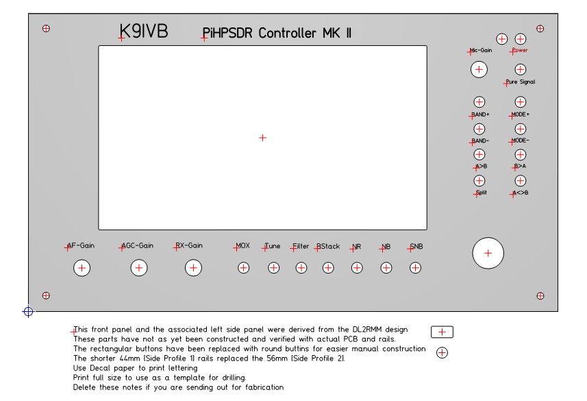
Below is the front panel I plan to
construct, but with some different graphics.
Changed the rectangular push buttons to round to make home
construction easier.
There are two Front Panel Express design files in the
BOM_Extra
Info_05032020.zip
download along
with an X , Y drill file [PiHPSDR_FP_Holes_K9IVB_05032020.pdf].
I have not been able, so far, to
reconcile the drill file for the Front Panel with the PCB drill file with
any degree of accuracy.
In the future I plan to glue a copy to a piece of
cardboard and drill out the holes after I finish building up my 2 PCBs
I am planning to convert to all English measurements: 10" x 5 1/2" to 6" panel, still subject to change.
* * * * * *
The attached [almost] fully sourced BOM and
other preliminary information
will provide some choices between the
rectangular pushbuttons and the round style
with some alternative case
construction ideas.
Note: After putting down the 42 10K 0805
resistors on the "front panel side" [they do just fit]
of the PCB I
have concluded that the parts should have been 0603 [Mouser #
603-AC0603FR-0710KL].
Also missed counting
R10 which is 0805 !
Will correct BOM after finishing assembly & test.
Two BOM errors
D2
should be BAS16J [Mouser # 771-BAS16J115] not BAS16W [wrong footprint]
L1,2,3,4
completely wrong part, should be Mouser # 623-2743021446 [last digit 6 is bulk 7 is T/R]
Another part error
R2 on
Schematic is 620 Ohm and BOM is 680 ohm.
620 Ohm is correct value to get 5V.
Still another error
The
2x20 header needs to be at least 13.58mm high so that the USB sockets clear
the PCB
PiHPSDR_Controller_MK_II_rev.2_BOM_05022020.pdf
The BOM also has a choice of 4 dual rotary
encoders or 4 single rotary encoders
which are interchangeable up until you
solder them into the PCB.
* * * * * *
If a couple of zeros after the first
significant digit of the Front Panel Express parts do not scare you off, you
might consider ordering the parts from that vendor. The DL2RMM design
has a deeper case and provision for a Hermes-Lite 2 as well.
NOTE: If
you are using the large 38x35mm D encoder [ENC6] you will need the bigger
Profile 2 extrusions.
My approach will be to use some hobby
plywood [1.5mm / 0.062" thick] or some window acrylic type material which is
much easier to hand machine than the aluminum, especially if you want the
small rectangular pushbuttons. This material could be used for front and /
or back panels and sides with the Front Panel Express Side Profile
Extrusions. Another alternative is to just get some 3/8" to 1/2" thick
hardwood [256mm / 10.08" Long] from Home Depot for the sides.
I am also
redoing the panel to be 10x6in [254x125.4mm] which will be easier to
construct
in the USA and will permit the use of wood sides.
Note: 1. the Left
hand side of the actual PCB should be only 0.07874in [2mm]
inside the panel,
so that there is easy access to the Raspberry PI outputs.
2. Leave some
clearance at the top of the panel for the other Pi I/O
which also overhang
the top edge of the PCB.
Home Depot has some "plastic" sheets:
Plaskolite
Non-Glare Picture Glazing UPC # 074507996548 8"x10"x0.050" @ $3.68
Optix Acrylic Sheet UPC # 769125010218 0.93"x11"x14" @ $6.67
Also 0.25":x2.5"x24" Poplar Board UPC #
728927310285 @ $2.58
Also now considering making 3D Printing [.stl] files for the side panels to fit FPE & wood sides.
* * * * * *
The original gerber files are available from github. See the link at the top of
the page.
I ordered my boards from JLCPCB and they had an issue with
the file extensions..
These drill files have never appeared in any gerber file
viewer that I have used, with out modifications.
Below is a copy of the gerber files that I used to
order my boards.
The only changes that were made were to the file extensions.
The Rev
2 artwork properly grounds the three address pins [14, 15,& 16] on IC1 the
MCP23017
PiHPSDR_MK_II_Rev.2_JLCPCB_Gerber.zip
Notes:
1. Any Gerber file is completely readable in any text editor.
2. They usually contain comments, with some descriptive information about the files.
3. If you wish to decode the actual data, not in the comments, you will have to refer
to the Gerber and Excellon formatting documents [see links below].
4. https://www.ucamco.com/en/gerber
5. Spec: The_Gerber_File_Format_specification.pdf
6. Excellon: https://gist.github.com/katyo/5692b935abc085b1037e
Free On-line Gerber Viewer: https://gerber-viewer.ucamco.com/index.html
* * * * * *
Stay tuned

You can contact me with QRZ info